To show version info, please click on the desired FlexiCAD version.

Download the latest version of FlexiCAD4 here:

This update expands the interfaces for even smoother data transfer to third-party programs and refines the control of export and display options.

Improved stability and reliability:

  • Consistent point scaling: A problem with scaling measurement and location points has been fixed. These are now displayed correctly even when a drawing is opened with units other than those currently preset in FlexiCAD.
  • Reliable export of “From Layer” objects: We have ensured that objects with the pen color “From Layer” are consistently included in all export scenarios.
  • Object thickness
    • In the “General Settings,” the validation for object heights has been adjusted: The value “0” is now accepted correctly without a
      warning message regarding negative values appearing.
    • For the French language version, the selection of special symbols has been translated.

Enhanced functionality

  • Precise export control by layer & style: Exporting to specific layers is now based exclusively on the specified pen color or pen style. The dependency on the general layer color has been removed in favor of more precise control.
  • Advanced color dialog & line type: In the advanced color dialog, the line type “From layer” can now be explicitly set as a style, which provides more flexibility in the drawing structure.

New features

  • Extensive upgrade of the .egi export
    • Room elements: All internal room elements are now exported as obstacles, which significantly increases visibility and planning reliability
      when transferring to kitchen programs.
    • Softronik extension: Specific element texts have been added for export to Softronic.
  • XML export version 1.4 available
    • From now on, XML export in version 1.4, also supports the export of images (compatible with HiCAD 2026 SP1).
    • A new export menu allows you to conveniently choose between XML versions 1.3 and 1.4.
  • New export format SmartWOP (.xml): Exports an XML file for the SmartWOP software.

This comprehensive update focuses on expanding functionality, optimizing interoperability with other programs, and further improving stability and user-friendliness.

Improved stability and reliability:

  • 2D projection, protection against geometry changes: If a 2D projection is performed on arcs or circles that have been moved to a non-parallel plane, the function is now disabled and a corresponding message is displayed in FlexiCAD to prevent unwanted geometry changes.
  • Copying elements (Ctrl+C / Ctrl+V), correct text alignment: The issue where copied text could appear rotated on a free layer has been fixed.
  • Display plane points, correct scaling of block symbol: The scaling of the block symbol for “Display plane points” has been corrected so that the display is now accurate even when working in units other than millimeters.
  • Calibrate self-defined room element, suitable measurement methods: The selection of calibration methods has been corrected so that only the methods suitable for the element are active.
  • Plumb CAD points, display message adjusted: The misleading message on the Flexijet display has been removed. Now, as usual, the next step (approaching the angle at a height of 30 mm) can be performed by triggering a measurement.

Enhanced functionality

General operation and stability

  • Opening larger files is no longer a problem: The internal process for opening FlexiCAD files has been revised so that files larger than 800 MB can now be opened without any problems.
  • Drawing units, consistency guaranteed: When opening a drawing that was created in a different unit of measurement, the drawing is now automatically scaled to the unit of measurement currently set in FlexiCAD. This ensures that you always work in the correct unit of measurement.
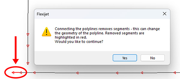
  • Optimized repetition of the “Connect Endpoints” function for polylines:
    • After the confirmation prompt, the function now remains active when you click “No.” This allows you to repeat the process immediately without restarting the function.
    • The Notification Window is now positioned so that it does not cover the polyline, allowing you to see any changes at all times.
  • Chamfering, faster working: The function can now be conveniently repeated by right-clicking in the drawing area.
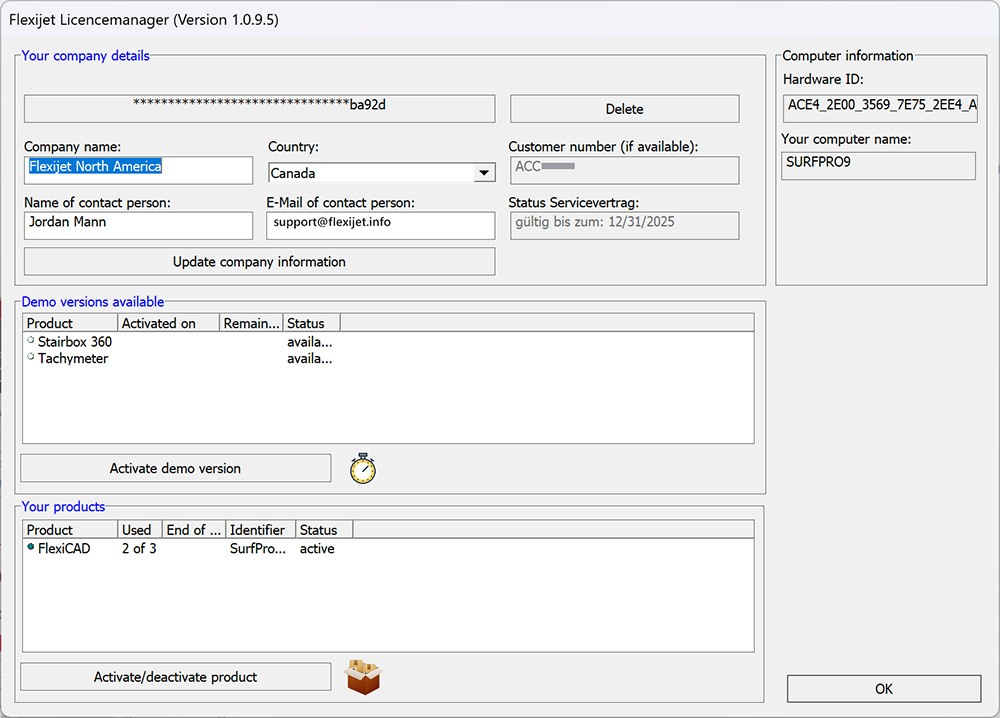
  • License Manager, customizable contact person: Customers now have the option to customize the contact person in the License Manager.
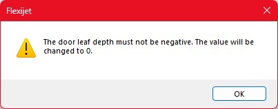
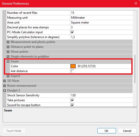
  • Prevent negative wall thicknesses: Under the general settings for “3D View,” you can now prevent negative wall thicknesses from being entered.

Measurement and CAD functions

  • Measure floorplan, automatic folder creation: If no project folder has been created yet, it will now be created automatically as soon as the “Measure floor plan” function is started.
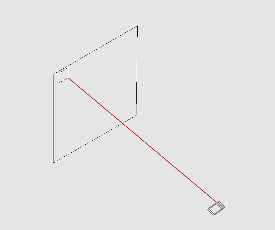
  • Smarter approach to CAD points: The “Show multiple CAD-points/show multiple CAD-points perpendicular” function has been improved and now always selects the point closest to the last point—for a more efficient measurement process.
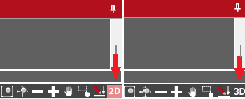
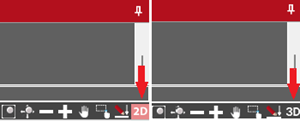
  • 2D snap mode, clearer visualization: The icon for 2D snap mode now adapts and displays “2D” to better indicate activation.
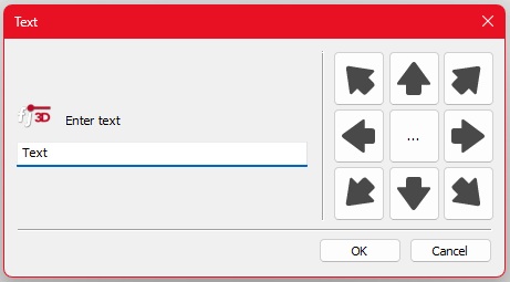
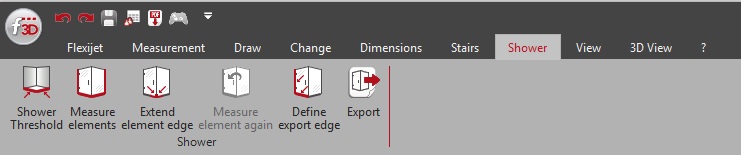
  • Shower module: New help images and more flexible export
    • Various help images have been added to schematically illustrate the input expectations.
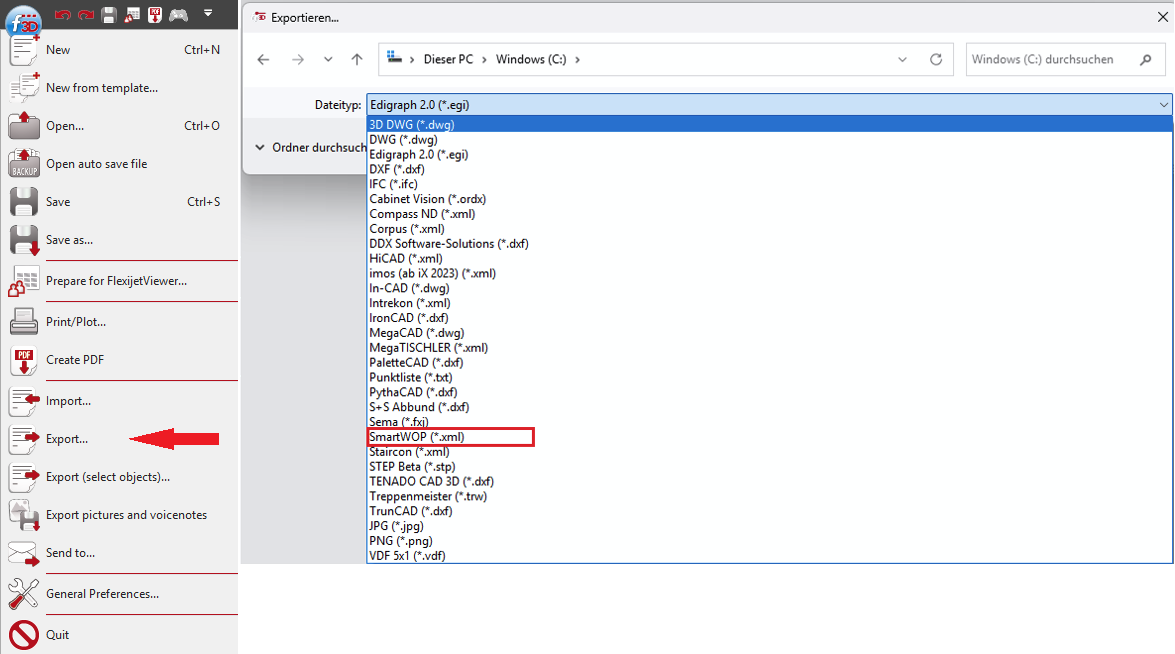
    • The export function in the “Shower” tab now allows you to select the folder to be exported, which is very helpful for projects with multiple measured showers.

Interoperability and export

  • Export to Compass: Relative image paths
    • The path to the images is now specified as a relative path in the Compass XML. This simplifies opening the files, as the image folder no longer needs to be specified manually (Compass software should be kept up to date).
    • Crash-proof image imports (staircase measurements): To prevent the image import from crashing if an image is missing, a default image is now inserted. This allows all other images to be imported correctly and the import to be completed.
  • Special characters in text, improved AutoCAD export: Texts ending with the ^ (circumflex) character, which could cause an error in AutoCAD, are now automatically appended with a space at the end during export.
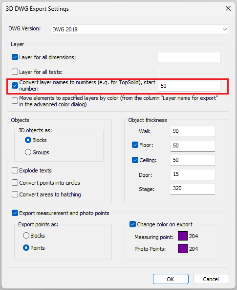
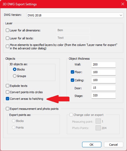
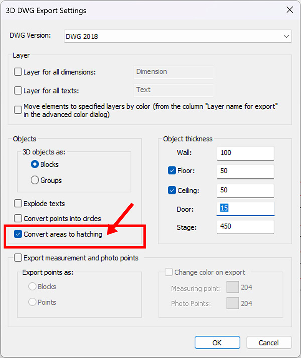
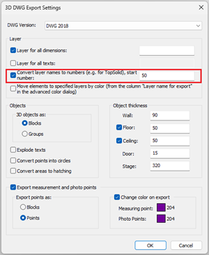
  • 3D DWG export, convert layer names to numbers: This function is now also available when exporting a 3D DWG.
  • English stair templates added: Stair templates for millimeter and inch settings have been added to the English templates.

New features

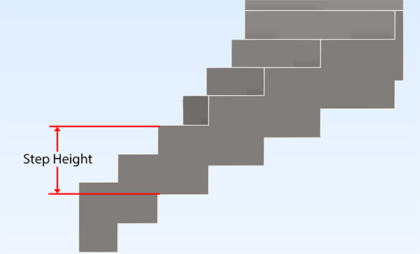
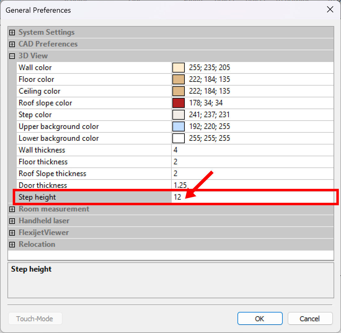
  • Stair module, advanced step planning: A new feature is the option to enter a step height that is automatically deducted from the bottom edge of the riser. This makes it easier to create planning-relevant contours for risers.
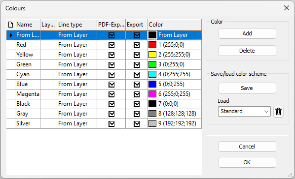
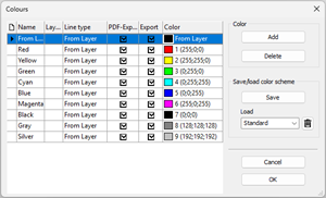
  • Advanced color dialog: More export control
    • The color dialog now offers additional options for specifying the line type
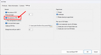
    • A checkbox can be used to control whether objects should be included in the export (e.g., DWG/PDF) or not for each color.
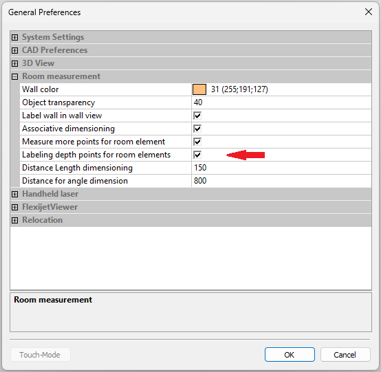
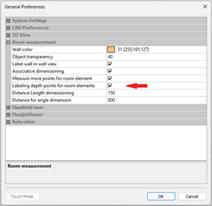
  • Depth points as stamps for room elements: This function allows depth points for room elements to be inserted as stamps. This provides important additional information, especially when sharing PDF files.
  • Extended export to Staircon (.xml): The export has been extended to now also support arcs, circles, points, and element colors (requires FlexiCAD 4.2.0.0 and Staircon version 2025.1).
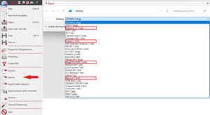
  • New export format Corpus (.xml): Exports an XML file for the Corpus software. A separate interface from Corpus is required.
  • New export format MegaTISCHLER (.xml): Exports an XML file for the MegaTISCHLER software. A current version of MegaTISCHLER is required.
  • New export format EGI (.egi): A new export format .egi has been added, which is mainly used for data transfer to kitchen programs. (Note: Elements such as niches, roller shutter belts, and heating are not usually imported via .egi; an additional dimensioned PDF transfer is recommended).

Stability and Reliability:

  • Improved: The Export function now checks the integrity of room elements. If the room element “Inswing Door” is defined with an invalid negative value for the door leaf depth, a notification is displayed, and the value is automatically set to 0 to ensure error-free exports.
  • Improved: When calling the function “Export, Select Objects…”, the correct export dialog is now reliably displayed, making the export process clearer and more efficient.
  • Improved: For the “Options for Auto Diemensions” function, a default dimensioning style has been set for angle and radial dimensions. This ensures that two decimal places are correctly displayed for angle dimensions, even if no specific style was previously selected.
  • Improved: The setting “Convert Areas to Hatching” in the export dialog now remembers your last choice. The checkbox is no longer automatically active for every export, saving you time and allowing for more consistent use of the export functions.

Stability and Reliability:

  • Staircon Export: The scaling issue that occurred during Staircon exports when FlexiCAD was set to inches has been resolved.
  • Layer Names: A bug where layer names for dimensions and text were ignored during export and replaced with numbers has been fixed.
  • OTF Fonts: OTF fonts have been removed from the list of text styles as they are not supported in FlexiCAD.
  • Digitize Hatch: A bug that allowed parallel actions to be performed during the “Digitize Hatch” function has been fixed to prevent unintended behavior and crashes.

Flexijet Smart Remote

  • A bug has been fixed that could prevent more than one audio note from being recorded.
  • Resume location is now supported on the Flexijet Smart Remote.

Enhanced Functionality

  • Resume Location: When the “Resume Location” function is selected on the Flexijet display and no location points exist yet, a corresponding message is now shown.
  • Series of Measurement Along Path: The function has been adjusted. The entered distance (e.g., 150 mm) is now considered the maximum distance. FlexiCAD automatically adjusts the distance to ensure the path’s endpoints are accurately reached.
  • Battery Capacity: A warning message is now displayed when the Flexijet’s battery capacity reaches 15% and 5%.

New Features

  • Scribe Tabs: This function allows you to create a notch, for example, on the wall side of a countertop. This allows the plate to be manufactured with fewer cuts.

    More information here: Manual “Scribe Tabs”
  • Options for auto dimensions: This new function allows for the flexible configuration of automatic dimensioning.


    More information here: Manual “Auto-Dimension”
  • Project Elements Perpendicular to a Plane: Project elements exactly perpendicular to a selected plane.
  • Offset and Delete: This function creates a parallel copy of an object and deletes the original in a single step.
  • Text/Label Function: When creating text or labels, you can now directly specify a rotation angle.


  • Seam: In the general settings, you can now specify whether a distance should be prompted for the automatic separation of cut edges.
  • TrunCAD Export: A new export for the TrunCAD software is available. It exports only the floor created with the “Measure Floor Plan” function, which eliminates the need for manual adjustments in FlexiCAD. [Placeholder for image from export menu]
  • IN-CAD Export: This export does not just create a classic 3D DWG file. Additionally, an XML file with image coordinates and the corresponding images are saved in a “project folder.” In IN-CAD, this folder can be loaded via a special Flexijet import, making the 3D model and all images taken by the Flexijet directly available. [Placeholder for image from export menu]

New Module: Shower

This module makes it possible to quickly and easily capture the relevant contours for a glass shower.

  • Automatic Offset: Offset dimensions can be automatically inserted to create an offset from the measured contour.
  • Line Straightening: If an edge or wall is measured with multiple points (polyline), the module automatically creates a straight line that represents the largest possible dimension.
  • Export Options:
    • When exporting via the new “Shower” ribbon, only the straightened lines are exported. This is ideal for transferring data to the Smart Glazier software.
    • If you also want to export the original lines, you can still use the classic export via the “F3D > Export…” menu.

More information here: Manual “Shower”

Improved Stability and Reliability:

  • Improved 3D Display:

    • Optimized 3D Display: Objects without a defined type and with a negative object height are now always displayed correctly in the 3D view. This ensures clear and reliable visual control of your projects. (This was a display issue only; data export was always correct).
    • More Consistent 3D View: Floor and Ceiling are now always displayed in the 3D view, regardless of export settings. Their visibility can still be conveniently controlled using the familiar buttons.
  • More Reliable Tools:

    • More Reliable Seam-Tool: The ‘Seam’ function now works more precisely and processes diagonal objects as expected.
    • More Robust 3D Object Creation: You can now create 3D objects from polylines more smoothly! The function is more fault-tolerant and automatically cleans up inaccuracies like duplicate points (segment length 0).
    • Correct Display in Digitze Hatch: The spatial distribution of measurement points from the ‘Digitize Hatch’ function is now displayed precisely and correctly again in the plan view (Improvement compared to version 4.0.2.0).
    • Automatic Dimensioning: For complete dimensioning, the ‘Floor’ folder is now correctly considered again by the automatic dimensioning function as intended.
    • More Convenient Calculator Usage: The integrated calculator remembers your inputs better! Values confirmed with the ‘Enter’ key now reliably appear in the history of recently used values.

Enhanced Functionality:

  • Enhanced Total Station Interface:

    • With an active Total Station connection, the Flexijet symbol is now displayed in FlexiCAD.
    • After a measurement, a red laser line in the drawing visualizes the last measured point. This significantly facilitates orientation.
  • Important: Default for Simplify Polyline:

    • The default tolerance has been reduced from 9° to 0.2° to achieve higher accuracy during simplification.
    • Note: Please check this setting under ‘General Settings’ > ‘CAD Settings’ in FlexiCAD and adjust it to your requirements if necessary.

English

Bugfixes: 

  • The PDF tool now correctly displays title block elements with color 7(black/white), even if the background is black. 
  • The PDF tool now outputs scaled blocks (installation symbols) correctly.  
  • The Round tool now works correctly with polylines. 
  • Stamp values are now displayed correctly with ‘Digitize Hatch’. In some cases, the values were inverted.  
  • ‘Show CADpoints from the drawing is now correctly aborted if the process is interrupted by the user. 
  • The import process using ‘File > Import is no longer canceled when the user presses “Enter” in PC mode with calculator input. 
  • The File Explorer when using “Import” or “Import Drop-in” no longer displays the contents of ZIP folders that cannot be opened – only files which can be opened are displayed. 
  • When measuring vertically (hand laser) with a base point only(without distance measurement), points are now correctly projected onto the active plane. 
  • When measuring vertically with a handheld laser, the automatic zoom is now only performed after the vertical line has been drawn. 
  • With ‘Show Multiple CADpoints (Perpendicular)’, the pause time can now also be skipped on the Flexijet 3D 2 or on the Flexijet Smart Remote app. 
  • The on-screen keyboard no longer closes after each letter in the text fields of ‘Draw a Sink or Cutout’ in touch mode. 
  • Trimming a line segment that is too short no longer deletes the line completely. 
  • The umlauts symbol is now correctly displayed in PDFs. 
  • Fixed issue where the laser module could shut down unexpectedly and require a restart of the Flexijet. 
  • After assigning an object height, the drawing is now automatically regenerated to reflect the changes. 
  • The warning during the Compass export is now displayed correctly. 
  • Fixed an issue where measurement coordinates and mouse click points were not accepted during an auto-save operation. 
  • FlexijetStone: The Wall function now correctly defines the layer, even if ‘Align to Object’ was previously used.  

Improvements: 

  • The ‘About FlexiCAD’ dialog now shows the next recommended service date, providing a quick and easy overview of your system’s maintenance needs.
    In addition, the ‘About FlexiCAD’ dialog now includes the contact information of your contact person, so you can get help quickly and easily 
  • The size of the license activation window has been adjusted and reduced to ensure correct display at lower screen resolutions on client PCs.
    FlexiCAD Licensemanager window
  • The HiCAD XML output has been significantly expanded to support custom walls, floors, ceilings, sloping ceilings, 3D objects, and surfaces, greatly improving data integration and interoperability with other systems. 
  • When connecting endpoints to polylines and other elements, the correct segment of the polyline is now used, instead of always the last segment. If this removes segments of the polyline, a message is displayed and the elements that are removed are highlighted.
    Connect Endpoints of polylines image 
  • A new, user-friendly update dialog now informs you about available updates. This dialog gives you the option to find out about optional service contracts, or to view the update information directly and download the update – without any login information. 

Features: 

  • Adjustable step height: The flexibility in staircase planning has been increased! The height of the stair treads can now be adjusted both in the general settings and in the export dialog for 3D-DWG and IFC.

     
  • Convert Faces to Hatch: For improved compatibility and easier editing, a new feature has been added that allows you to convert Face objects to Solid Hatch during export.
    3D DWG Export Areas to hatching
  • Advanced Calculator: The calculator input has been enhanced with adjustable shortcuts and now displays a history of the most recently used values, which significantly increases efficiency and ease of use.
     
  • Project Elements Parallel to Layer: Project elements parallel to a layer! A new feature allows for precise projection of elements parallel to a selected plane, providing greater flexibility in measuring and accuracy in editing. 
  • Output Parts list to PDF: Extended Parts List functionality! Items from your Parts List can now be seamlessly inserted into the PDF output on a separate page.
    PDF tool with Parts list option highlightedPDF output showing parts list thumbnail
  • Create Gap: Precise joint creation made easy! A new modification tool allows you to create a joint with a defined width by selecting an intersecting line. Seam button in Flexijet Stone 4
  • Create Seam: Precise object seaming made easy! A new modification tool allows you to create a Seam by selecting an intersecting line, making it easy to divide objects into two parts. Optionally, a distance can be entered for moving the objects apart. Gap Button Flexijet Stone 4
  • Automatic dimensioning with options: Complete control over automatic dimensioning! A new feature allows for detailed adjustment of automatic dimensioning, including:  
  • Selecting the Dimension Style for Length Dimensions 
  • Selecting the Dimension Style for Angular Dimensions 
  • Selecting the Dimension Style for Diameter Dimensions 
  • Specifying a Range of Length for Automatic Line Dimensioning 
  • Activation/deactivation of automatic diameter dimensioning of circles.
     
  • Simplify Polyline: Optimize your polylines with ease! A new feature allows you to simplify complex polyline contours within a set tolerance, reducing the number of points while maintaining the desired accuracy for simplified machining. 
  • Multi Polyline (Simplified): Measure and optimize complex polylines in one step! This new command allows you to create a polyline whose contour is automatically simplified within a specified tolerance when the measurement is complete. This function is an efficient extension of the ‘Multi Polyline’ function. 
  • Create Backsplash with polar tracking: Draw kitchen backsplashes with precision and ease! The ‘Backsplash’ command now supports Polar Tracking, so you can easily create kitchen backsplashes at specific angles and orientations.


This update brings important improvements and optimizations to FlexiCAD to make your working experience even more efficient and enjoyable.

Improved stability and reliability:

  • The measurement preview on the Flexijet display is now always displayed correctly, even if the additional function “Measure on sphere” is activated during the “Define location” function.
  • The 3D view and the 3D DWG export have been optimized and now ensure that 3D objects are displayed and exported correctly.
  • The layer structure in the project explorer has been improved to ensure the stability and consistency of your projects.
  • The “Trim” and “Round” functions have been revised and now deliver precise results in all cases.
  • The import of colors has been optimized so that the setting “Use colors ‘From layer’ as pen color” now has the desired effect.
  • A bug has been fixed in FlexijetStone that affected reliable image generation in the “Approach and photograph” function.

Extended functionality:

  • FlexijetStone: The “Insert sink section” function now takes the layer color into account for an even more precise display.
  • FlexijetStone: The “Approach and photograph” function has been optimized and now allows you to enter an offset on horizontal layers. In addition, the function can now only be selected when a Flexijet is connected to ensure smooth operation.
  • Switching to the fine drive by pressing and holding the scroll wheel on the Flexijet is now even more reliable.

New functions:

FlexiCAD:

  • New design of the FlexiCAD interface: Function buttons with submenus are now separated to make it easier to recognize that further commands are available.
  • The “Manual room from floor plan” function has been added to the submenu of the “Room from floor plan” function. The corners of the floor plan must be selected manually.
  • The function “Show angles between planes”: Displays all angles of the active layer to other layers in the drawing. Accessed by right-clicking on a folder and selecting Layer > Show angles between layers.
  • It is now possible to create 3D objects from closed polyline contours: Selecting the polyline and defining the object height and type (e.g. 3D object, wall, floor, ceiling, surface, fume cupboard).
  • New “3D view” tab: Interactive preview of the model in different visualization styles to check the details before exporting.
  • New export interfaces:
    – IFC export
    – 3D DWG export
    – XML export to Intrekon and HiCAD
    – MegaCAD export of a 3D DWG with images
    – Export to Cabinet Vision for simple rooms (XML+DXF)
  • In the 3D view, the model can now be rotated with Shift + middle mouse button.
  • New license server for more efficient license management.

Flexijet:

  • A horizontal plane can now be created on the Flexijet by entering a Z value. This function is available when creating a new horizontal plane or when “measuring floor plan”.
  • Fine adjustments to the Flexijet laser are now possible using the scroll wheel: when the command is active, the fine drive can be activated by pressing and holding the scroll wheel to precisely control the Flexijet. The direction of travel can be changed by tapping the arrow in the new menu.
  • The Flexijet interface can now be mirrored to the PC via the livestream; commands can be controlled using the mouse.
  • The laser module is automatically switched off when inactive to save battery power and service life. The switch-off time can be adjusted in the “general settings”; the laser is automatically activated when there is activity.
  • Several functions can now be switched directly on the display in the “polyline” drawing command: Polyline as line/straight line or arc (optionally with tangential transition).
  • The Flexijet can now be operated via a network cable (special adapter required). If required, please contact support.
  • After completing the “Align to object” function, a confirmation is shown on the display.
  • Context-related help images are now displayed during the execution of a command to visually support the correct measurement position. For simple commands such as the polyline, the corresponding symbol is displayed in the preview to make the active command clearly recognizable.

Flexijet Smart Remote App:

  • Various commands can now be started directly via the Smart Remote app.
  • Navigation through the folders in the project explorer is now possible.
  • The user interface has been adapted: If no command is active, the app is in the command view; if a command is active, remote control mode is automatically activated.

Improvements:

FlexiCAD:

  • The quick dimensioning now considers lines with a radius at the end and measures to the intersection of the next line instead of just to the start of the radius.
  • The “Number parts” function now includes the set pen color.
  • Measurement series are no longer aborted if a point cannot be measured; instead, the point is skipped and the measurement is continued.
  • Revision of the export dialog: The selection of various DWG, DXF and IFC formats is now available directly in the export dialog, which increases clarity.
  • When moving a plane, all elements except the measuring points are moved to the new plane, eliminating the need for manual 2D projection.
  • The “Export” > “Export subfolders to separate files” function now allows you to select specific folders for export.
  • Paragraphs in notes are now correctly taken into account in the PDF output.
  • The livestream window can be configured so that it always remains in the foreground to prevent it from moving to the background when commands are executed.

Flexijet:

  • Images taken with the camera live image active use the currently set zoom level; the zoom is reset when the live image is deactivated.
  • The function “Measure door, not relevant to planning” on the Flexijet now uses the last values saved in FlexiCAD instead of the default values. Changes must still be made in FlexiCAD.

Bugfixes:

FlexiCAD:

  • An error has been fixed where the “Show CAD points from drawing” function was continued although it was canceled.
  • Fixed a bug where a user-defined installation symbol could incorrectly create a new layer in FlexiCAD.
  • Fixed a bug that caused the steps not to be rotated to the XY plane when exporting a 3D staircase with the “Arrange elements” and “Rotate elements to XY plane” options.

Flexijet:

  • A bug has been fixed that made it possible to activate an installation icon by double-clicking on the Flexijet 2x display, which could cause a software crash.
  • Fixed a problem where the letter keyboard was displayed although a number input was expected.
  • Correction of a bug that caused the keyboard to be displayed in the German layout after restarting the Flexijet, even if another language was previously selected.